The Motor Driver
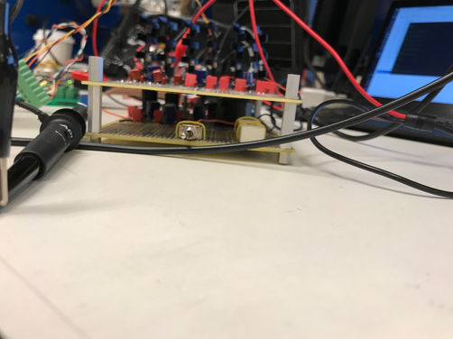
Describing this project just as a motor driver is a bit of an oversimplification. This project was part of my final project for 6.131, a power electronics class. The project has three main components. First the brushless DC motor controller (all it does is give the right signal to the motor, depending on the rotational position of the motor, second a "buck converter" that reduces the voltage of the input depending on the desired speed, and third a boost converter that increases the voltage outputted by the motor when breaking. Due to the similar topology, the boost and the buck converter were built onto the same circuit, as shown in the following pictures. All of the circuits were initially controlled by analog chips, but later via a Cypress PSOC (programmable system on chip).
The final system can be summarized in the following figure:

The Motor Driver
The motor driver consists of a 3-phase H-bridge and a controller.
For the 3-phase H-bridge, I used six IRF1407 MOSFETs, MUR120 diodes and IR212 MOSFET controllers.
Now all that was left for the controller to do is decide which set of coils gets powered based on the rotational position of the motor. This can either be done by using analog circuitry (as done in the beginning), or digital micro-controllers, such as Arduino, or a PSOC (as used in the end). The PSOC was programmed to measure the output of the three Hall effect sensors to decide in which of the states the motor is (as seen in the scope shot on the right) and then apply power to the corresponding MOSFETs.
In the beginning, when I switched from the analog chips to a microcontroller, the motion of the motor was quite choppy and would sometimes stop entirely. This was solved by applying the three following fixes. First I modified the code so it would apply an averaging filter over two or three measurements, second I added a capacitor-resistor analog filter to the Hall-effect sensors, and third I forced the motor to not skip any steps. All these steps were needed in order to make sure that noise-attributed spikes did not make the PSOC think the motor was in the wrong location. Afer applying these fixes, the motor worked much smoother than before.
The Buck & Boost Converter
This part of the project was by far the most interesting one. The goal of the system is to be able to control the speed of the motor while running, as well as the breaking force/charging rate when it is breaking. In order to do that, one needs two voltage controllers. One to control the voltage fed to the motor and one to control the voltage fed to the batteries from the motor. I assumed that our voltage source (or batteries) will always be higher than what is needed to drive the motor full-speed. Thus I designed a circuit to work as a buck converter in one direction (towards the motor) and as a boost converter the other way around. This allows one to control the speed of the motor by changing the duty speed on the buck converter and control the breaking force by changing the duty cycle of the boost converter. It was relatively easy designing such a circuit on one board, as one is the mirror image of the other with a capacitor in its output. After designing for the values of the components I built and tested the design and it worked fine.
Furthermore, since everything was already being controlled by the PSOC, I found it relatively easy adding a PID (proportional, integral, derivative) feedback loop to the system in order to control the speed of the motor. This allowed the motor to run at the desired speed regardless of the source voltage (as long as it satisfied a minimum). Implementing PID feedback system for the boost converter was much harder, as they are not inherently stable systems.


